
Introduction to Thevenin’s Theorem in Electrical Engineering
In electrical and electronics engineering, one of the biggest challenges students face is analyzing complex circuits with multiple sources and resistors. Solving such circuits using only Kirchhoff’s laws often becomes time-consuming and confusing.
This is exactly why Thevenin’s Theorem is considered one of the most powerful network theorems in circuit analysis. It provides a systematic method to simplify any linear electrical circuit into a much smaller and more manageable form.
By mastering Thevenin’s Theorem, you gain the ability to:
Reduce complex circuits into simple equivalents
Quickly calculate load current and voltage
Understand how a circuit behaves from the load’s perspective
What Is Thevenin’s Theorem?
Thevenin’s Theorem states that:
| Any linear, bilateral electrical network consisting of resistors and independent sources can be replaced, as seen from two terminals, by an equivalent circuit containing a single voltage source (Thevenin Voltage, Vth) in series with a single resistance (Thevenin Resistance, Rth).
This equivalent circuit delivers the same voltage and current to the load as the original complex network.
->In other words, from the outside, a complex circuit behaves like a simple battery and resistor.
Key Conditions for Applying Thevenin’s Theorem
Thevenin’s Theorem is applicable when:
The circuit is linear
Components include resistors, independent voltage sources, and current sources
The analysis is done between two terminals
It is not directly applicable to:
Non-linear components (diodes, transistors without linearization)
Time-varying non-linear circuits
Why Thevenin’s Theorem Is So Important
Thevenin’s Theorem is important because it:
Reduces calculation effort drastically
Makes repeated load analysis easy
Helps engineers design stable and efficient circuits
Improves conceptual understanding of circuit behavior
Is frequently asked in engineering exams and interviews
In real engineering practice, no one solves the entire circuit again and again—Thevenin’s equivalent is used instead.
Understanding Thevenin Voltage (Vth) Clearly
Thevenin Voltage (Vth) is defined as:
The open-circuit voltage across the load terminals
Measured when the load resistor is completely removed
Why open-circuit?
Because Vth represents the maximum voltage the circuit can provide to the load.
-> Think of Vth as the potential strength of the circuit.
Understanding Thevenin Resistance (Rth) Intuitively
Thevenin Resistance (Rth) represents:
The internal resistance of the entire network as seen from the load terminals
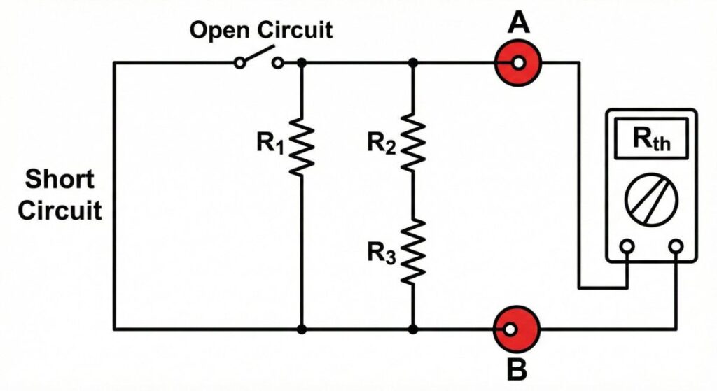
How to Find Rth:
Remove the load
Turn off all independent sources
Voltage source → short circuit
Current source → open circuit
Calculate equivalent resistance across terminals
-> Rth tells us how much the circuit resists current flow to the load.
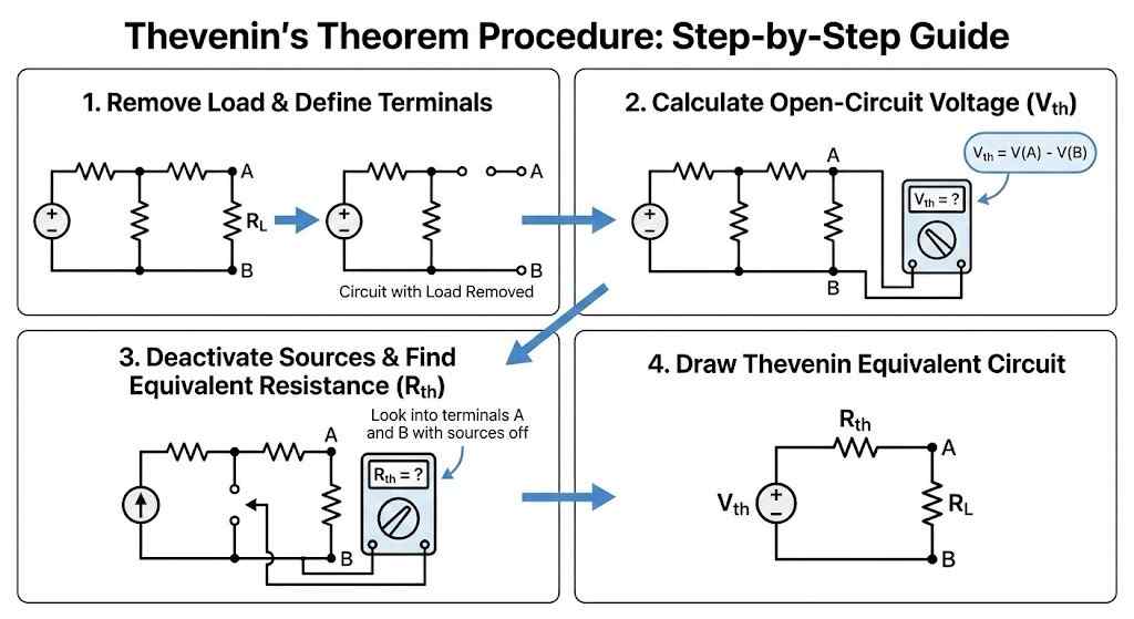
Step-by-Step Procedure to Apply Thevenin’s Theorem
Step 1: Identify and Remove the Load
Locate the component where output is required and disconnect it.
Step 2: Find Open-Circuit Voltage (Vth)
Apply KVL, KCL, or voltage divider rule to find the voltage across open terminals.
Step 3: Find Equivalent Resistance (Rth)
Deactivate sources and simplify the resistor network.
Step 4: Rebuild the Circuit Using Vth and Rth
Reconnect the load to the Thevenin equivalent circuit.
Thevenin’s Theorem Mathematical Expression
Once the Thevenin equivalent is obtained:
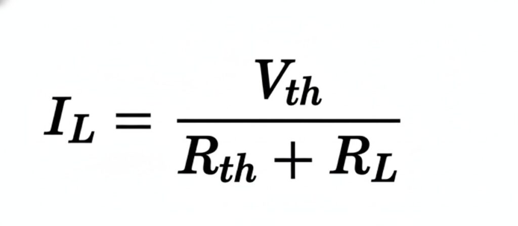
This single equation replaces multiple loop or nodal equations.
Deep Example Insight (Conceptual)
Instead of solving:
3 mesh equations
2 node equations
Multiple substitutions
You solve:
One voltage source
Two resistors in series
That’s the true power of Thevenin’s Theorem.
Thevenin’s Theorem in Practical Electronics
Thevenin’s Theorem is used in:
Power supply modeling
Battery internal resistance estimation
Sensor signal conditioning
Embedded system input analysis
PCB troubleshooting
Analog circuit design
Every real power source behaves like a Thevenin equivalent.
Thevenin’s Theorem vs Norton’s Theorem (Conceptual View)
Both theorems describe the same circuit behavior:
Thevenin → voltage perspective
Norton → current perspective
Engineers switch between them depending on convenience.
Common Mistakes
Forgetting to remove the load before Vth
Turning off dependent sources incorrectly
Mixing up Rth and RL
Applying Thevenin to non-linear devices
Missing polarity while calculating Vth
Avoiding these mistakes alone can increase exam scores significantly.
Real-Life Analogy
Think of a power bank:
Voltage rating → Vth
Internal losses → Rth
No matter what device you connect, the power bank’s behavior is governed by these two parameters.
Conclusion: Mastering Thevenin’s Theorem
Thevenin’s Theorem in electrical circuit analysis is not just a topic—it’s a foundation skill. It teaches you how to simplify complexity, think like an engineer, and analyze circuits efficiently.
Once mastered, it makes advanced topics like power electronics, analog design, and embedded systems much easier to understand.
About pluntx

Pluntx is India’s leading platform for electronics and 3D printing solutions, offering a wide range of products like Arduino, Raspberry Pi, drone parts, sensors, 3D printer components, and more. We also provide expert CAD design services and affordable 3D printing, starting at just ₹49. Click here to explore our extensive collection of electronics and prototyping tools. Be sure to follow us on Instagram and YouTube, where we regularly share tutorials, tips, and updates on everything from Arduino projects to drone technology. Pluntx delivers precision and quality. Our mission is to empower creativity through technology and simplify the journey from concept to creation.