In electronics, accuracy is everything. Whether you’re building a prototype, debugging a PCB, or testing a power supply, your ability to measure electrical parameters correctly determines how fast—and how well—you solve problems.
At Pluntx, where we work extensively with electronics components, 3D printing systems, embedded hardware, and rapid prototyping, one tool is used more than any other:
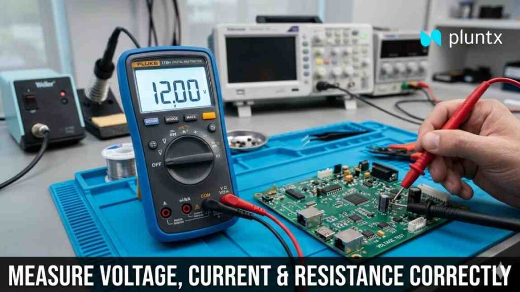
| The Digital Multimeter (DMM)
Yet, despite being so common, many beginners—and even some intermediate users—make critical mistakes while using it. These mistakes can lead to:
Incorrect readings
Damaged components
Blown multimeter fuses
Even safety hazards
This blog is a deep, practical, and easy-to-understand guide to help you master measuring:
Voltage
Current
Resistance
Along with real-world tips, mistakes to avoid, and professional insights from Pluntx workflows.
Understanding the Multimeter
A multimeter is a versatile measuring instrument used to analyze electrical circuits. It combines multiple tools into one:
Voltmeter → Measures voltage
Ammeter → Measures current
Ohmmeter → Measures resistance
Modern digital multimeters (DMMs) also include:
Continuity testing
Diode testing
Capacitance measurement
Frequency detection
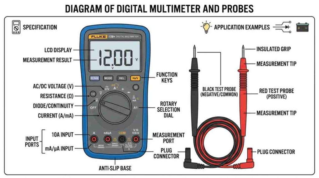
Multimeter Basics: Ports and Probes
Before measuring anything, you must understand the ports:
COM (Common) → Black probe always goes here
VΩmA Port → Used for voltage, resistance, and small current
10A Port (or High Current Port) → Used for measuring large currents
Golden Rule:
Always double-check probe placement before switching measurement type.
1. Measuring Voltage Correctly
What is Voltage?
Voltage is the potential difference between two points in a circuit. It tells you how much electrical “pressure” is pushing current through the circuit.
Types of Voltage
DC Voltage (V⎓) → Batteries, microcontrollers, power supplies
AC Voltage (V~) → Household electricity, AC adapters
Step-by-Step Procedure
Insert probes:
Black → COM
Red → VΩ port
Set dial to:
DC (V⎓) or AC (V~)
Place probes in parallel:
Across the component or source
Read the value on the display
Why Parallel Connection?
Voltage is measured across two points, not through the circuit. That’s why probes are placed in parallel.
Real-World Example
You’re testing a 12V SMPS powering a PCB:
Expected: ~12V
If you read:
0V → broken connection
5–9V → voltage drop / overloaded supply
>12V → faulty regulator
Pro Tips
– Use auto-range if available
– For manual meters, start with higher range
– Keep probes steady to avoid fluctuations
2. Measuring Current Correctly
What is Current?
Current is the flow of electric charge through a conductor. It is measured in Amperes (A).
Why Current Measurement is Tricky:
Unlike voltage, current cannot be measured by simply touching two points.
⚠️ You must insert the multimeter into the circuit path.
Step-by-Step Procedure:
- Move red probe to:
- mA port (small current) OR
- 10A port (high current)
- Set dial to:
- DC current (A⎓) or AC current (A~)
- Break the circuit
- Connect multimeter in series
- Power ON the circuit
- Read current value
Why Series Connection?:
Current must pass through the meter, so it has to be part of the circuit.
Real-World Example:
Testing an embedded system:
- Expected current: 80mA
- If reading shows:
- 0mA → open circuit
- 500mA+ → short circuit or faulty component
Critical Safety Tips:
‘X’ Never connect meter across battery in current mode
‘X’ Always start with highest current range
‘X’ Switch back probe after measuring current
Common Mistake (Very Important):
Many beginners forget to move the probe back from the current port and try to measure voltage.
Result: Short circuit + blown fuse
3. Measuring Resistance Correctly
What is Resistance?:
Resistance is the opposition to current flow, measured in Ohms (Ω).
Step-by-Step Procedure:
- Turn OFF power supply
- Discharge capacitors
- Insert probes:
- Black → COM
- Red → VΩ
- Set dial to Ω
- Place probes across component
Why Power Must Be OFF?:
External voltage interferes with resistance measurement and can damage the multimeter.
Real-World Example:
Testing a resistor:
- Expected: 1kΩ
- Results:
- ~1kΩ → working
- OL (Open Loop) → broken resistor
- 0Ω → shorted
Accuracy Tip:
For precise measurement:
✔ Remove one leg of resistor from circuit
✔ Avoid touching probe tips with fingers (affects reading)
Continuity Testing (Bonus):
Continuity mode helps check if a path is complete.
- If beep sound → connection exists
- No beep → broken connection
Practical Uses
- PCB trace testing
- Wire continuity
- Fuse checking
- Connector verification
Common Mistakes to Avoid
| Mistake | Consequence |
|---|---|
| Measuring current in parallel | Short circuit |
| Measuring resistance in live circuit | Wrong reading / damage |
| Wrong probe port | No reading / blown fuse |
| Not breaking circuit for current | Invalid results |
| Ignoring range limits | Overload error |
Advanced Insights (For Engineers)
Burden Voltage in Current Measurement:
When measuring current, the multimeter introduces a small internal resistance.
This can slightly affect sensitive circuits.
Input Impedance in Voltage Measurement:
High-quality multimeters have high input impedance (~10MΩ), ensuring minimal circuit disturbance.
Measuring in Switching Circuits:
For circuits like:
- SMPS
- PWM motor drivers
- Microcontroller systems
Use:
✔ Stable grounding
✔ Short probe contacts
✔ Oscilloscope for dynamic signals
Conclusion
A multimeter is more than just a tool—it’s your window into the behavior of your circuit.
At Pluntx, every successful prototype, every tested PCB, and every reliable product begins with accurate measurement.
If you learn to measure voltage, current, and resistance correctly:
- Your debugging becomes faster
- Your designs become better
- Your confidence as an engineer grows
About pluntx

Pluntx is India’s leading platform for electronics and 3D printing solutions, offering a wide range of products like Arduino, Raspberry Pi, drone parts, sensors, 3D printer components, and more. We also provide expert CAD design services and affordable 3D printing, starting at just ₹49. Click here to explore our extensive collection of electronics and prototyping tools. Be sure to follow us on Instagram and YouTube, where we regularly share tutorials, tips, and updates on everything from Arduino projects to drone technology. Pluntx delivers precision and quality. Our mission is to empower creativity through technology and simplify the journey from concept to creation.