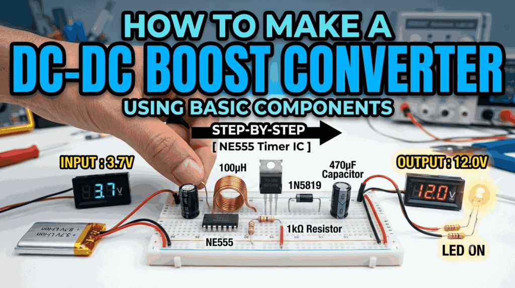
A DC-DC boost converter is one of the most useful power electronics circuits for beginners and electronics enthusiasts. It converts a low DC voltage into a higher DC voltage efficiently using switching techniques. These converters are widely used in battery-powered devices, solar systems, LED drivers, electric vehicles, and portable electronics.
In this blog, we will learn how to build a simple boost converter using basic electronic components and understand its working principle step-by-step.
What is a Boost Converter?
A boost converter is a type of switching regulator that increases the input voltage to a higher output voltage.
Example:
- Input Voltage: 5V
- Output Voltage: 12V
The circuit stores energy in an inductor and releases it at a higher voltage level using rapid switching.
Basic Working Principle
The boost converter works in two stages:
1. Switch ON State
- Current flows through the inductor.
- The inductor stores energy in its magnetic field.
- The diode blocks current flow to the output side.
2. Switch OFF State
- The switch turns OFF suddenly.
- The inductor releases stored energy.
- The released energy adds to the input voltage.
- Output voltage becomes greater than input voltage.
This ON-OFF switching happens thousands of times per second.
Components Required
Here are the basic components needed to build a simple boost converter:
| Component | Value | Purpose |
|---|---|---|
| Inductor | 100µH | Stores energy |
| MOSFET / NPN Transistor | IRFZ44N / TIP122 | Switching device |
| Diode | 1N5819 Schottky | Fast recovery rectifier |
| Capacitor | 470µF | Output filtering |
| Resistor | 1kΩ | Gate/Base limiting |
| PWM Source | NE555 Timer | Generates switching pulses |
| Power Supply | 5V DC | Input voltage |
| Load | LED / Small motor | Output device |
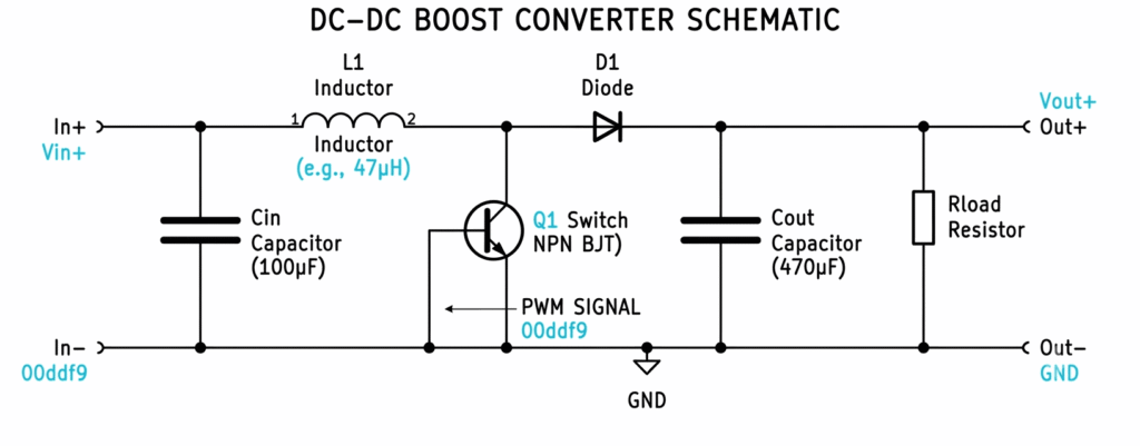
Circuit Diagram Overview
Main Connections:
Input Side
- Connect the positive terminal of the power supply to one side of the inductor.
Switching Section
- Connect the other side of the inductor to:
- Drain/Collector of transistor
- Anode of diode
Output Side
- Connect cathode of diode to:
- Positive terminal of capacitor
- Output terminal
Ground
- Connect all grounds together.
Simple Boost Converter Block Diagram
Role of Each Component
1. Inductor
The inductor is the heart of the boost converter. It stores energy when current passes through it and releases energy when switching stops.
2. Switching Transistor
The MOSFET or transistor rapidly switches ON and OFF using PWM signals.
3. Diode
A Schottky diode is preferred because it has low forward voltage drop and fast switching speed.
4. Capacitor
The capacitor smooths the pulsating output voltage and reduces ripple.
5. PWM Generator
The NE555 timer IC generates pulse-width modulation signals to control switching frequency.
Using NE555 Timer for PWM
The NE555 timer can generate square wave pulses for controlling the MOSFET.
Recommended Frequency
- 20kHz to 100kHz
Higher frequency:
- Smaller components
- Better efficiency
- Reduced ripple
Step-by-Step Assembly
Step 1: Gather Components
Collect all components and verify their ratings.
Step 2: Build PWM Circuit
Configure the NE555 timer in astable mode.
Step 3: Connect Inductor and MOSFET
Carefully wire the switching stage.
Step 4: Add Diode and Capacitor
Ensure correct diode polarity.
Step 5: Test the Circuit
Apply 5V input and measure output voltage using a multimeter.
Expected Output
| Input Voltage | Output Voltage |
|---|---|
| 3.7V | 5V – 9V |
| 5V | 9V – 15V |
| 9V | 15V – 24V |
Output depends on:
- Duty cycle
- Switching frequency
- Load current
- Inductor value
Important Design Formula
Output Voltage Equation
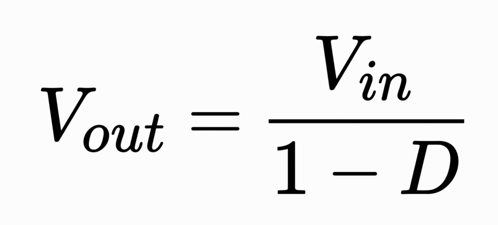
Where:
- Vin= Input voltage
- D = Duty cycle
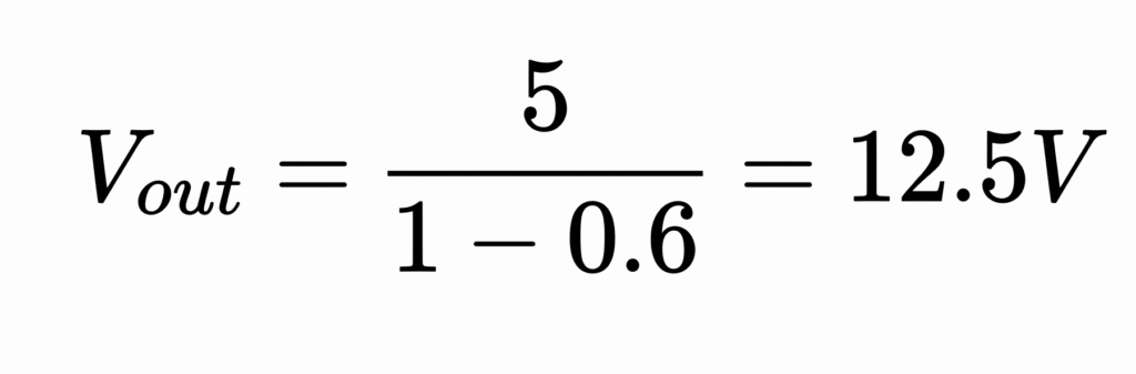
Example:
If:
- Input = 5V
- Duty cycle = 0.6
Then:
Applications of Boost Converters
Boost converters are used in many real-world applications:
- Power banks
- Solar charge controllers
- LED drivers
- Electric vehicles
- Battery-powered devices
- Mobile charging circuits
- Robotics projects
Advantages
- High efficiency
- Compact design
- Low power loss
- Portable applications
- Easy to build
Common Problems and Solutions
| Problem | Possible Cause |
|---|---|
| No output voltage | Wrong diode polarity |
| Low output voltage | Incorrect PWM frequency |
| Heating issue | Poor MOSFET selection |
| Ripple in output | Small capacitor value |
Tips for Better Performance
- Use Schottky diodes for efficiency.
- Choose low ESR capacitors.
- Keep wires short.
- Use proper heat sinks for MOSFETs.
- Optimize PWM duty cycle.
Final Thoughts
Building a DC-DC boost converter is an excellent beginner-friendly power electronics project. It helps in understanding switching regulators, inductors, PWM control, and efficient power conversion techniques.
By using simple components like an NE555 timer, MOSFET, inductor, diode, and capacitor, you can create a functional voltage booster for many electronics projects.
Whether you are an engineering student, hobbyist, or maker, this project is a great way to explore practical electronics and power conversion systems.
About pluntx

Pluntx is India’s leading platform for electronics and 3D printing solutions, offering a wide range of products like Arduino, Raspberry Pi, drone parts, sensors, 3D printer components, and more. We also provide expert CAD design services and affordable 3D printing, starting at just ₹49. Click here to explore our extensive collection of electronics and prototyping tools. Be sure to follow us on Instagram and YouTube, where we regularly share tutorials, tips, and updates on everything from Arduino projects to drone technology. Pluntx delivers precision and quality. Our mission is to empower creativity through technology and simplify the journey from concept to creation.